Static Control Flooring – Conductive or Dissipative?

The selection of static control flooring for use as a part of a footwear/flooring system for controlling electrostatic charges on personnel is not a new topic. In many cases the interested readers may be looking for information to educate themselves, but in most cases, they are looking to answer two specific questions. Which flooring material do I need? Which one is better?
There is no cookie cutter, cookbook, response that can be given. Many of the important considerations to be reviewed exceed those of Electrostatic Discharge (ESD) control alone. Examples include: cost, appearance, longevity, maintenance, safety, weight rating, and many others. For the purpose of this discussion we will focus on the crucial considerations needed for ESD control using ANSI/ESD S20.20 as the basis. For the majority of industry and personnel handling ESD sensitive items, a Human Body Model voltage (HBM) of less than 100 volts generated by personnel is adequate.
When procuring a flooring material, the interested party is typically given two choices, conductive or dissipative, both defined by their electrical resistance (See ANSI/ESD STM7.1). This standard test method characterizes a conductive flooring material as having a resistance to ground of ≤ 1.0 x10⁶ ohms. A dissipative flooring material is one that has a resistance to ground >1.0 x 10⁶ ohms and < 1.0 x10⁹ ohms. Notice the clean precise cut-off of between the two at exactly 1.0 x 10⁶ ohms. What is so significant (insignificant) about this value?
Let’s look at how a static control flooring system is intended to function. The flooring systems’ purpose is to provide an electrical path, typically to ground, for personnel when used in conjunction with static control footwear (See ANSI/ESD STM9.1), for removal (equalization) of electrostatic charge. There are other options for connecting personnel to the flooring system, such as foot grounders, heel/toe grounders, booties and other devices (See ANSI/ESD SP9.2), but for the sake of this discussion we will use the generic term footwear to describe all methods.
It is not appropriate to discuss flooring without considering the necessity and impact of footwear. The two must work together.
Product qualification of each (i.e., footwear or flooring) is conducted individually; however, the end user must focus on how the parts function as a whole. For this ANSI/ESD S20.20 has two requirements, both of which must be met.
The first requirement is that the resistance of the person wearing footwear while standing on the flooring system shall be less than 1.0 x 10⁹ ohms
(per ANSI/ESD STM97.1).
Let’s consider the components of the footwear/flooring system and how they are connected. When calculating the total system resistance we need to include the resistance of the person, the footwear and the flooring.
Rtotal=Rperson+Rfootwear+Rflooring
As a practical example, a person has a typical internal resistance of 300 to 1000 ohms and dry skin resistance varies from 1,000 ohms up to 100,000 ohms. Footwear is available with resistances on the low end of approximately 5.0 x10⁵ ohms up to, for our discussion, the ANSI/ESD S20.20 limit, of 1.0 x 10⁹ ohms. Flooring as described above can be procured in conductive (≤1.0 x10⁶ ohms) and dissipative ranges (>1.0 x10⁶ ohms and < 1.0 x10⁹ ohms).
Given these values as an example, you can see that the main components of importance are that of the footwear and the flooring. The resistance of the person becomes somewhat negligible.
The second ANSI/ESD S20.20 requirement is that of maintaining a peak body voltage generation of a footwear/flooring system in combination with a person to less than 100 volts peak (per ANSI/ESD STM97.2). This is the more difficult, and truthfully, the more telling of the two requirements to be met.
To understand why, we need to explore the relationship that system resistance (ANSI/ESD STM97.1) plays in the removal (equalization) of electrostatic charge in comparison to the propensity for triboelectric charging (ANSI/ESD STM97.2) of the footwear and the flooring system.
The impact of system resistance is fairly easy to understand if we view it generically as a step response (tau) of an RC circuit, i.e., the time it takes to go from one initial voltage state (Vi) to a second final voltage state (Vf).
![]()
Note: 5 tau is considered to be the completed decay time.
For this example, the R is Rtotal of the footwear/flooring system and C is a person’s capacitance, typically 100 pF to 200 pF. If we take the capacitance as generally being a constant (150pF), the exponential decay then becomes based primarily on the Rtotal of the system. The higher the Rtotal of the system the longer the decay (tau) for any given start (1000 volts) and stop voltages (100 volts).
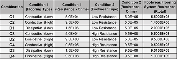 Table 1: Rtotal as a Function of Flooring and Footwear Combinations
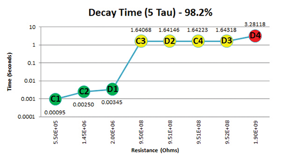 Figure 2: Decay Times for Flooring and Footwear Combinations (Logarithmic Scale)
 Figure 1: Decay Times for Flooring and Footwear Combinations
Conclusion
When selecting static control flooring, one should want to choose a footwear/flooring system where Rtotal is the lowest possible resistance and where the interactions between the footwear and flooring system provides the lowest triboelectric charging (voltage) as possible (See ANSI/ESD STM97.2).
You can see that dissipative flooring when used with low resistance footwear (D1) will provide similar decay times as compared to conductive flooring conditions (C1 and C2). Similarly the decay times for the combination of conductive and dissipative flooring with low and high resistance footwear (C3, C4, D2 and D3) also provide similar decay times. It is only the condition where we use dissipative flooring in combination with high resistance footwear that our decay times become troublesome.
It should also be mentioned again, that we have only focused on the resistance portion of the footwear/flooring system. The main purpose here was to demonstrate that the terms “conductive flooring” and “dissipative flooring” really serve no real purpose other than generic naming conventions. There is nothing special, as it relates to practical implementation, with the artificial line created between the two definitions at 1.0 x10⁶ ohms.
Footwear/flooring resistance is only one variable that one must consider to establish a successful program where body voltage on personnel is controlled. The second, and usually the more impactful of the two, is the interaction of the surface of the flooring with the contact area of the footwear. It is this interaction that will determine the rate or triboelectric charging. When selecting a footwear/flooring system, the user must balance the propensity for triboelectric charging versus the decay time for the given system. Selecting one where the conflict between the two, creates an environment where body voltage on personnel is maintained to predetermined, safe levels.
Referenced Publications
- ANSI/ESD STM7.1-2013 – Floor Materials – Characterization of Materials
- ANSI/ESD STM9.1-2014 – Footwear – Resistive Characterizations (not to include heel straps and toe grounders)
- ANSI/ESD SP9.2-2019 – Footwear – Foot Grounders Resistive Characterization (not to include static control shoes)
- ANSI/ESD S20.20-2014 – Protection of Electrical and Electronic Parts, Assemblies and Equipment (Excluding Electrically Initiated Explosive Devices)
- ANSI/ESD STM97.1-2015 – Floor Materials and Footwear – Resistance Measurement in Combination with a Person
- ANSI/ESD STM97.2-2016 – Floor Materials and Footwear – Voltage Measurement in Combination with a Person
- EOS/ESD Association, Inc. 7900 Turin Road, Bldg 3, Rome, NY 13440-2069, 315-339-6937, http://www.esda.org